12-2499 Fireguard Instruction Sheet
Open the original PDF document
View PDF12-2499 FIREGUARD ® Closer-Holder Device PUSH SIDE INSTALLATION INSTRUCTIONS
SARGENT
ASSA ABLOY
CAUTION: FAILURE TO INSTALL OR ADJUST PROPERLY MAY RESULT IN INJURY OR DAMAGE For assistance, contact SARGENT at 800-810-WIRE (9473) or www.sargentlock.com
NOTE: AN AUXILIARY DOOR STOP IS REQUIRED AT HOLD OPEN

CAUTION:
- 1. DISCONNECT ALL POWER BEFORE INSTALLATION.
- 2. ALL WIRING TO BE PERFORMED BY QUALIFIED PERSONNEL TO COMPLY WITH ALL APPLICABLE LOCAL CODES.
- 3. MAXIMUM WIRE SIZE IS 18 AWG.
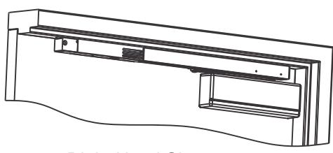
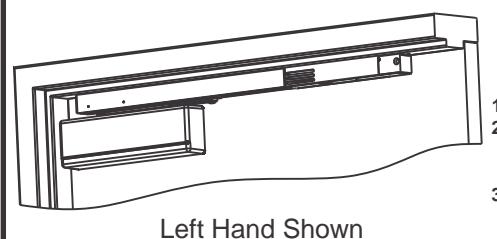
Right Hand Shown
- Use template on page 4. Drill and tap door for 12-24 machine screws and frame for 1/4-20 machine screws. Prepare hole for conduit. Do not drill through channel, as damage will occur voiding warranty.
- Install closer body to door with spring power nut away from hinge.
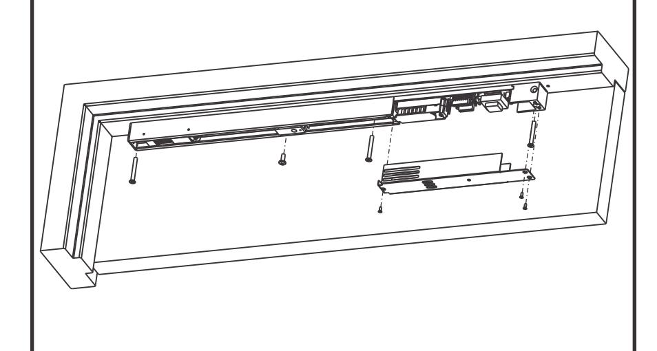
- Following local codes, attach cable or conduit to track. Secure track to frame with electronics away from hinge with screws provided.
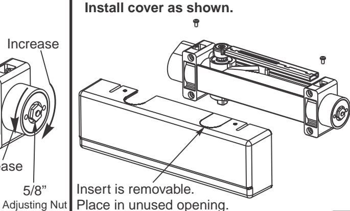
Wire unit as shown on Page 3; install cover as shown.
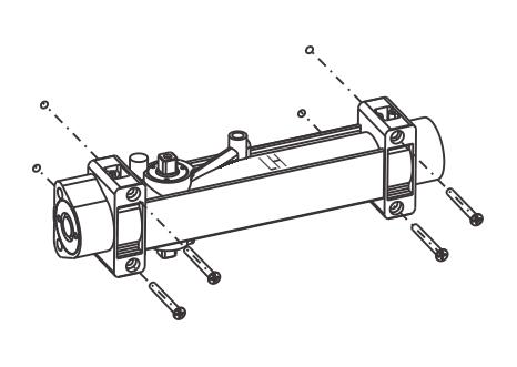
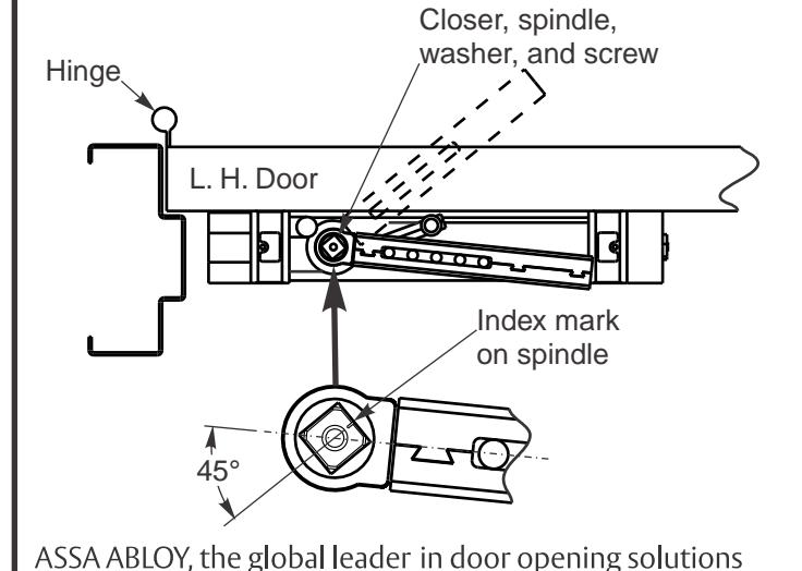
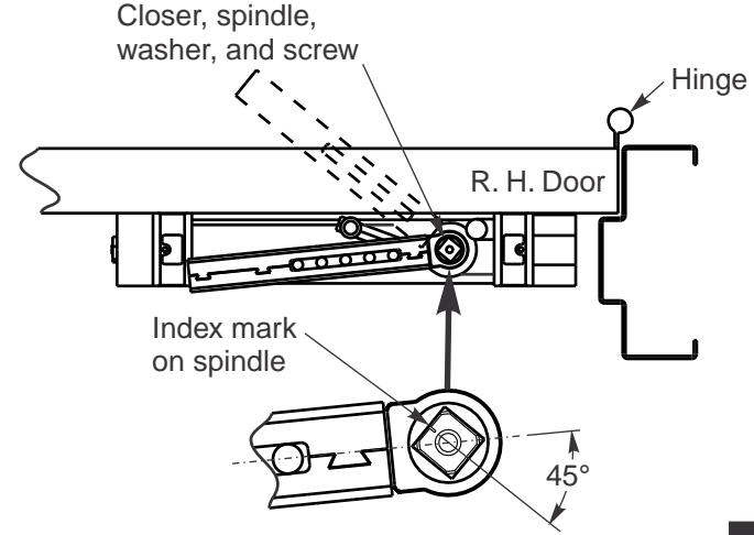
With wrench on bottom spindle, rotate spindle approximately 45°. Use screw and washer to secure main arm to top spindle with index mark as shown.
Copyright © 2015, Sargent Manufacturing Company, an ASSA ABLOY Group company, All rights reserved. Reproduction in whole or in part without the express written permission of Sargent Manufacturing Company is prohibited.
A8199 (10/15)
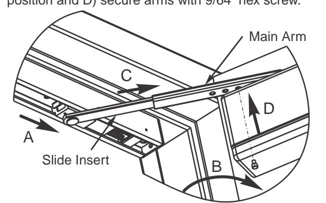
Adjust hold open angle by adjusting arm length: Range of 85° to 110° is obtainable. A) Place slider in hold-open setting, B) open door, C) insert slide insert into main arm. Open door to desired hold-open position and D) secure arms with 9/64" hex screw.
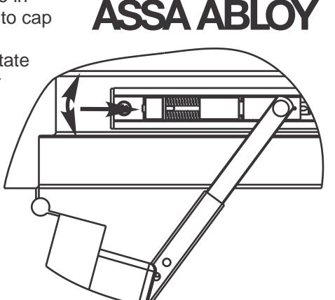
To adjust holding tension:
Insert 9/64" allen wrench thru hole in track end cap into cap screw in spring mechanism. Rotate allen wrench for desired tension.
SARGENT
FINAL ADJUSTMENT AND REGULATING PROCEDURES
6
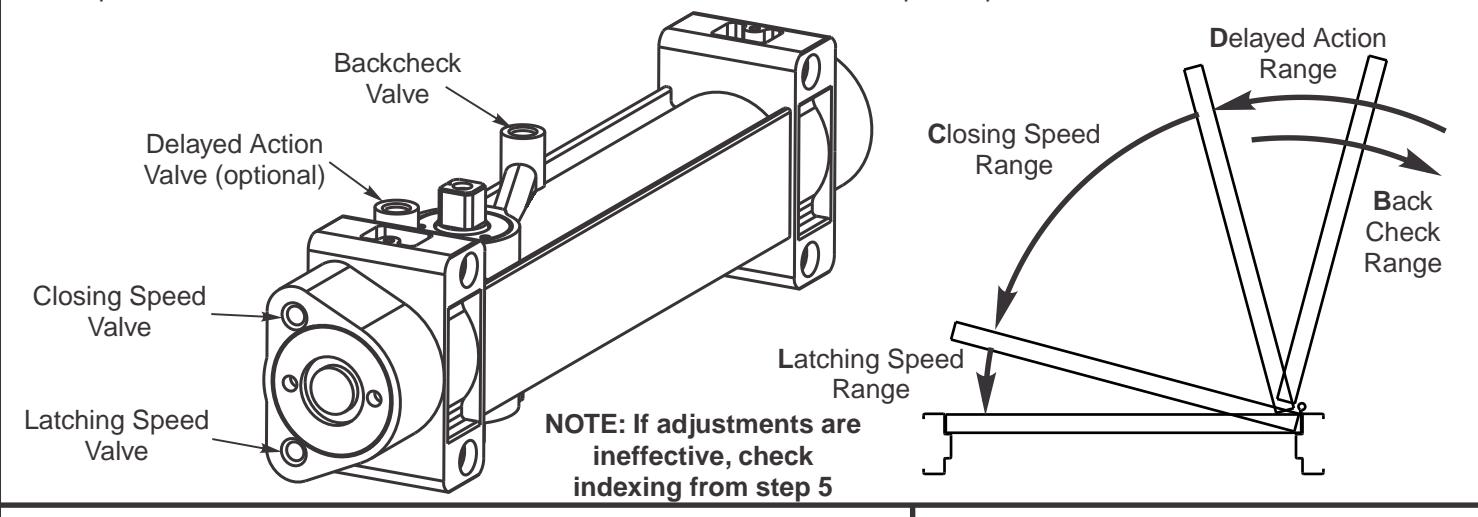
Closing and latching speed:
Turn valves clockwise to slow down or counterclockwise to speed up door movement.
Backcheck:
Turn valve clockwise to increase or counterclockwise to decrease.
CAUTION: SET VALVE FOR SLIGHT CUSHIONING EFFECT. NEVER USE THE BACKCHECK AS A DOOR STOP. ALWAYS USE A DOOR STOP TO STOP THE DOOR.
Delayed action feature (optional):
When provided, turn valve clockwise to slow down or counterclockwise to speed up door movement.
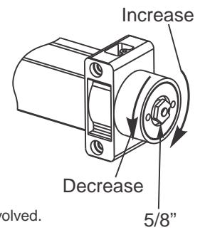
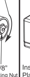
Adjust power to allow door to close and latch
| Number of Turns of Spring Power Adjusting Nut | ||
|---|---|---|
| Door Width (inches) | Exterior Doors | Interior Doors |
| 24 - 30 | 1 - 3 CCW | 1 - 3 CCW |
| 30 - 36 | Factory Set | Factory Set |
| 36 - 42 | 1 - 4 CW | 1 - 4 CW |
| 42 - 48 | 7 - 9 CW | 4 - 6 CW |
Adjusting door to close due to high draft conditions may exceed ADA standards. Consult local ordinances when fire doors are involved.
Copyright © 2015, Sargent Manufacturing Company, an ASSA ABLOY Group company, All rights reserved. Reproduction in whole or in part without the express written permission of Sargent Manufacturing Company is prohibited.
A8199 (10/15)
INSTALLER: LEAVE INSTRUCTIONS WITH BUILDING OWNER
CAUTION
- 1. Disconnect all power before beginning installation to prevent electrical shock and equipment damage.
- 2. Installer must be a trained, experienced service person.
- 3. All wiring must comply with applicable local electrical codes, ordinances and regulations.
- 4. Maximum wire size is 14AWG.
Wiring Diagram for Master to Companion
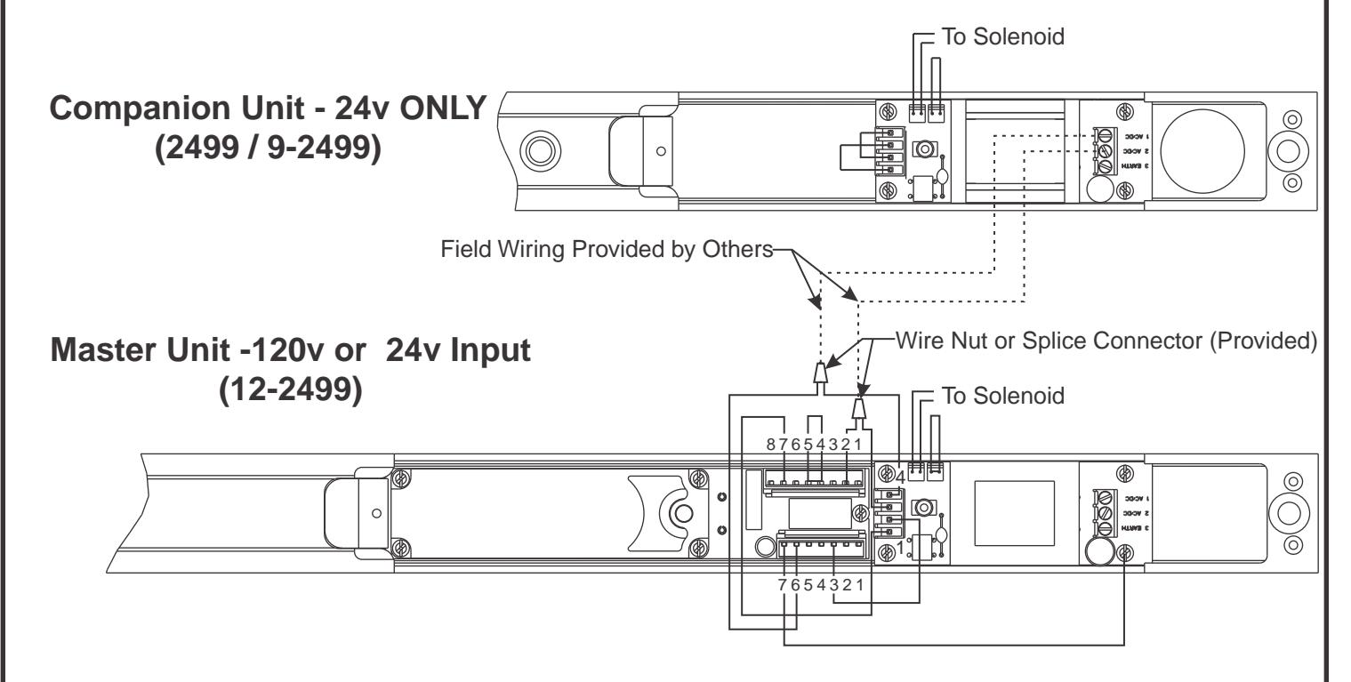
- Companion units are designed to work with 12- smoke detector units.
- Wire companion unit to smoke detector unit as shown on wiring diagram.
- Do not disconnect any existing wires on smoke detector unit's terminal strip.
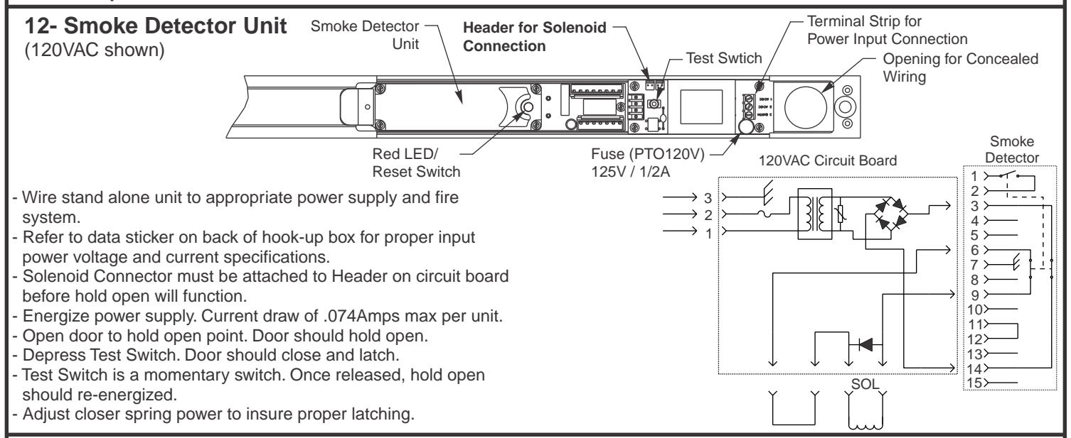
- Energize power supply. Current draw of .074Amps max per unit.
- Open door to hold open point. Door should hold open.
- Depress Test Switch on master unit. Doors should close and latch.
- Test Switch is a momentary switch. Once released, hold open should re-energized.
- Adjust closer spring power to insure proper latching.
express written permission of Sargent Manufacturing Company is prohibited.
Copyright © 2015, Sargent Manufacturing Company, an ASSA ABLOY Group company, All rights reserved. Reproduction in whole or in part without the
SARGEN ASSA ABLO 5-15/16 (151) Edge of stop (38) 2" Min stop 2-3/16 (56) 1-1/2 (38)Edge of stop (25)1-1/8 (29) hole — for Conduit Pan head machine screws " 3-7/8 35-5/16 (897)2-7/16 29-1/2 (62)(749)35-13/16 34-3/16 (910)machine screws (898)(4) #12 x 3" Wood Screws or #12-24 x 2-1/4" Flat head (3) 1/4-20 x 2" Flat head machine screws
Q Hinge: Butts, center hung or offset pivots
- 1. Reinforced metal doors and frames per ANSI
- A250.8 & SDI-100, 12 gauge recommended. 2. Left hand door shown, right hand opposite. 3. For narrow rail doors (minimum 3"), use 351-D NOTES:
(227)0
2 2 (51)
2-15/16 (75)
of stop Bottom
2-7/16 (62)
drop plate.
(486)
(302)
3-1/8
(2)
19