12-2469 Fireguard Instruction Sheet
Open the original PDF document
View PDF12-2469 FIREGUARD <sup>®</sup> Closer-Holder Device PULL SIDE INSTALLATION INSTRUCTIONS
SARGENT
ASSA ABLOY
CAUTION: FAILURE TO INSTALL OR ADJUST PROPERLY MAY RESULT IN INJURY OR DAMAGE For assistance, contact SARGENT at 800-810-WIRE (9473) or www.sargentlock.com
NOTE: AN AUXILIARY DOOR STOP IS REQUIRED AT HOLD OPEN
Use template on page 4. Drill and tap door for 12-24 machine screws and frame for 1/4-20 machine screws. Prepare hole for conduit. Do not drill through channel, as damage will occur voiding warranty.
Install closer body to door with spring power nut away from hinge. Left hand shown.
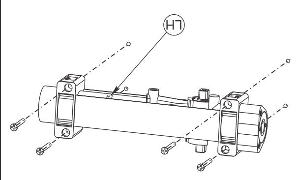
351 Closers are non-handed, RH must be on top for right hand doors and LH must be on top for LH doors.
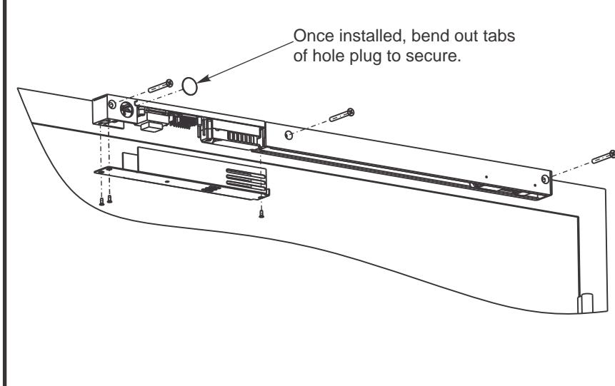
Following local codes, attach cable or conduit to track. Secure track to frame with electronics away from hinge with screws provided.
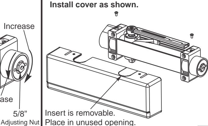
Wire unit as shown on Page 3; install cover as shown.
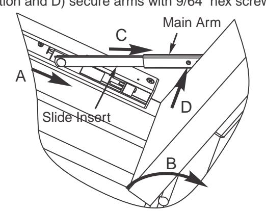
Adjust hold open angle by adjusting arm length: Range of 85° to 110° is obtainable. A) Place slider in hold-open setting, B) open door, C) insert slide insert into main arm. Open door to desired hold-open position and D) secure arms with 9/64" hex screw.
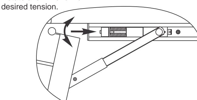
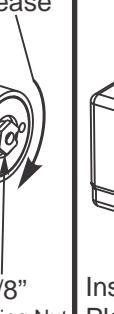
To adjust holding tension:
Insert 9/64" allen wrench thru hole in track end cap into cap screw in spring mechanism. Rotate allen wrench for

SARGENT
ASSA ABLOY
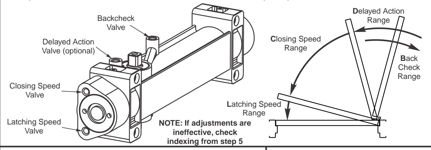
FINAL ADJUSTMENT AND REGULATING PROCEDURES
6
Closing and latching speed:
Turn valves clockwise to slow down or counterclockwise to speed up door movement.
Backcheck:
Turn valve clockwise to increase or counterclockwise to decrease.
CAUTION: SET VALVE FOR SLIGHT CUSHIONING EFFECT. NEVER USE THE BACKCHECK AS A DOOR STOP. ALWAYS USE A DOOR STOP TO STOP THE DOOR.
Delayed action feature (optional):
When provided, turn valve clockwise to slow down or counterclockwise to speed up door movement.
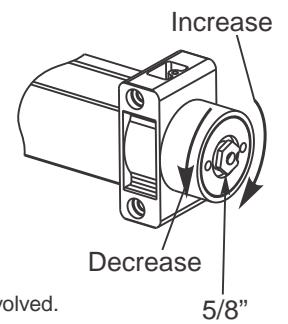
Adjust power to allow door to close and latch
| Number of Turns of Spring Power Adjusting Nut | ||
|---|---|---|
| Door Width (inches) | Exterior Doors | Enterior Doors |
| 24 - 30 | 1 - 3 CCW | 1 - 3 CCW |
| 30 - 36 | Factory Set | Factory Set |
| 36 - 42 | 1 - 4 CW | 1 - 4 CW |
| 42 - 48 | 7 - 9 CW | 4 - 6 CW |
Adjusting door to close due to high draft conditions may exceed ADA standards. Consult local ordinances when fire doors are involved.
Copyright © 2015, Sargent Manufacturing Company, an ASSA ABLOY Group company, All rights reserved. Reproduction in whole or in part without the express written permission of Sargent Manufacturing Company is prohibited. A8195 (10/15)
INSTALLER: LEAVE INSTRUCTIONS WITH BUILDING OWNER
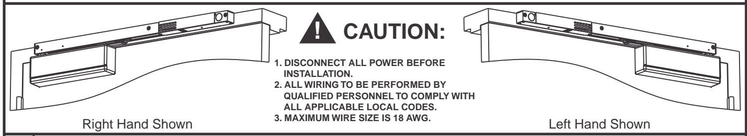
CAUTION
- 1. Disconnect all power before beginning installation to prevent electrical shock and equipment damage.
- 2. Installer must be a trained, experienced service person.
- 3. All wiring must comply with applicable local electrical codes, ordinances and regulations.
- 4. Maximum wire size is 14AWG.
Wiring Diagram for Master to Companion
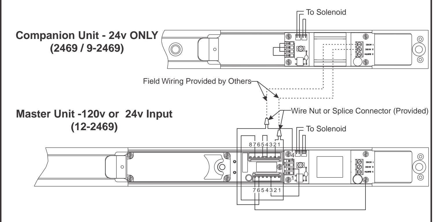
- Companion units are designed to work with 12- smoke detector units.
- Wire companion unit to smoke detector unit as shown on wiring diagram.
- Do not disconnect any existing wires on smoke detector unit's terminal strip.
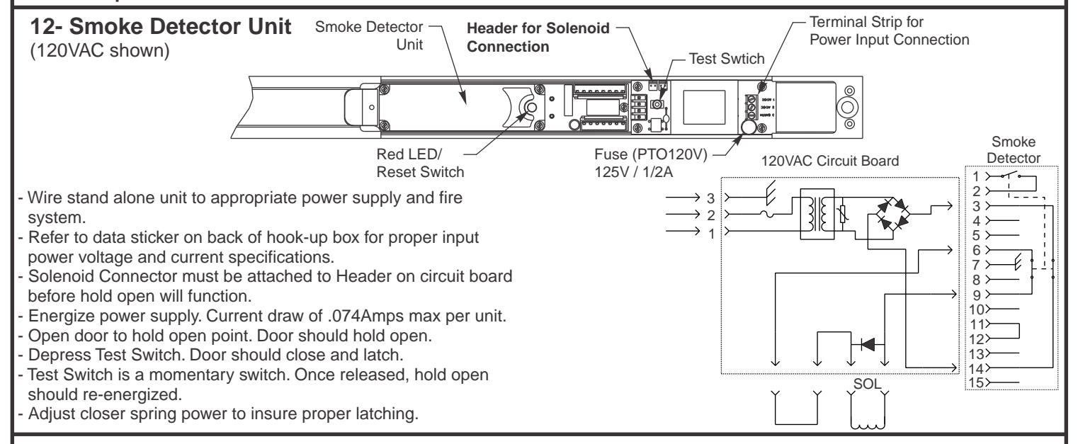
- Energize power supply. Current draw of .074Amps max per unit.
- Open door to hold open point. Door should hold open.
- Depress Test Switch on master unit. Doors should close and latch.
- Test Switch is a momentary switch. Once released, hold open should re-energized.
- Adjust closer spring power to insure proper latching.
express written permission of Sargent Manufacturing Company is prohibited.
Copyright © 2015, Sargent Manufacturing Company, an ASSA ABLOY Group company, All rights reserved. Reproduction in whole or in part without the
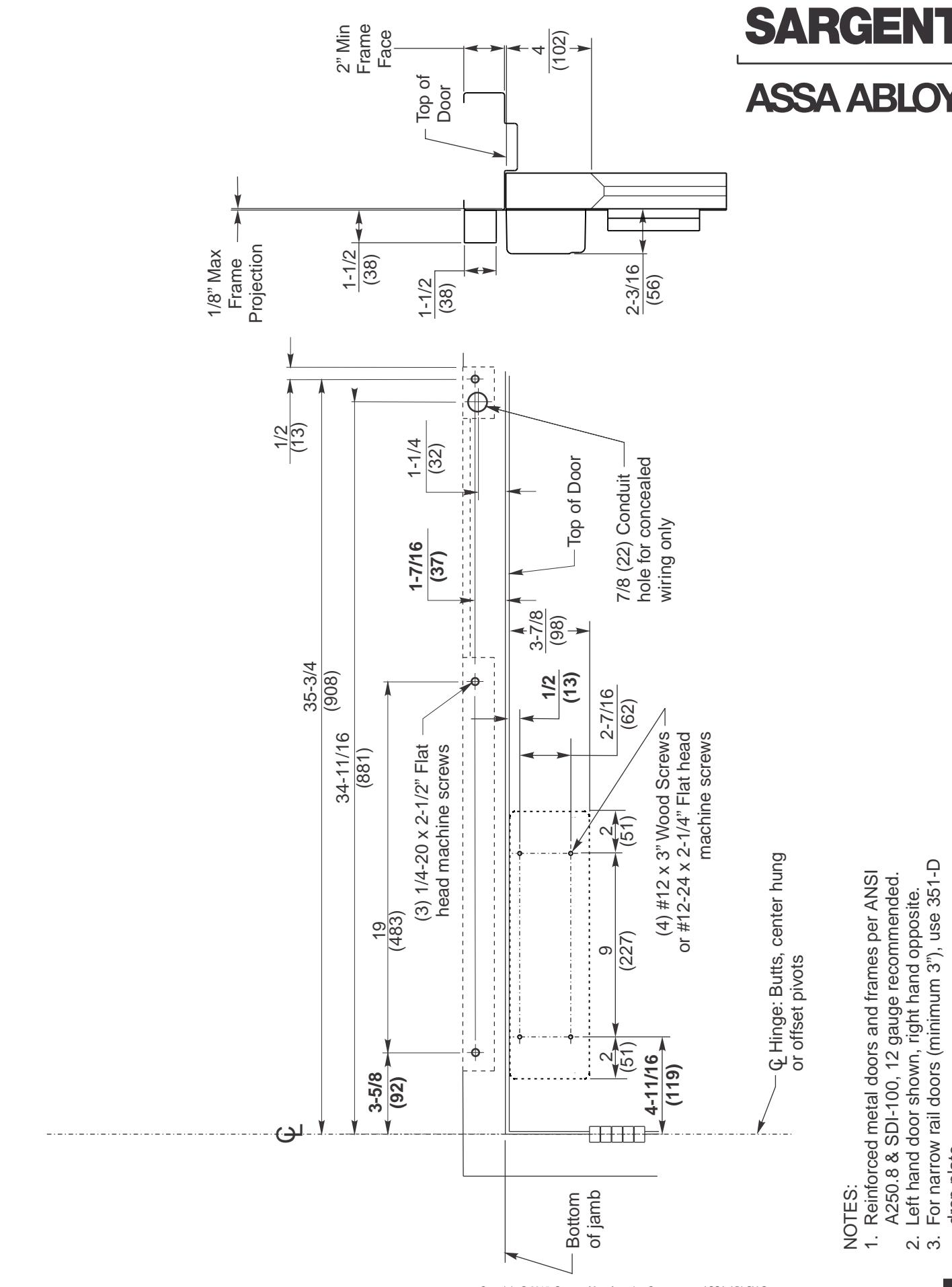
drop plate.
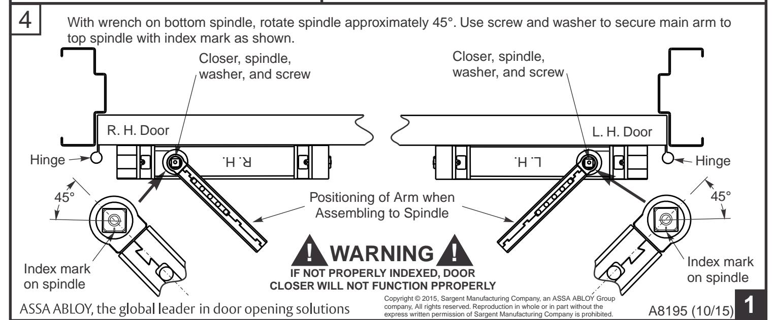
2. Left hand door shown, right hand opposite. 3. For narrow rail doors (minimum 3"), use 351-D
A250.8 & SDI-100, 12 gauge recommended.