10X Line Cylindrical Lockset Installation Instruction
Open the original PDF document
View PDFInstallation Instructions

10X Line Cylindrical Lockset
1 Tools Required
- #2 Phillips screwdriver Lever release tool (provided) 5/16" drill bit 1/8" drill bit 5/32" drill bit
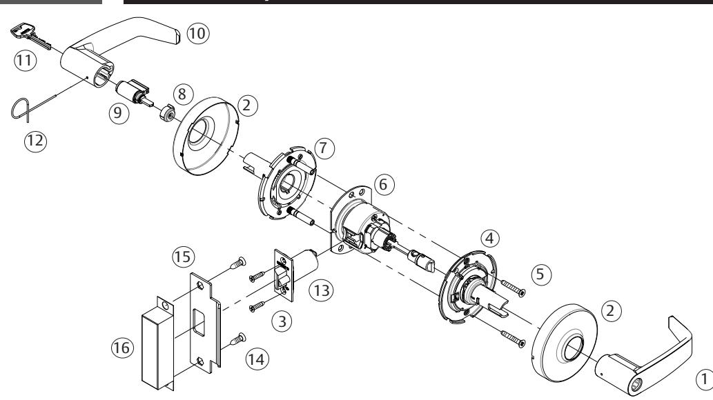
2 Product Components
| Fig. | Description |
|---|---|
| 1 | Inside lever handle |
| 2 | Rose/Scalp (2) |
| 3 | Screws - latch (2) #8-32 x 3/4" |
| 4 | Inside spring housing assembly |
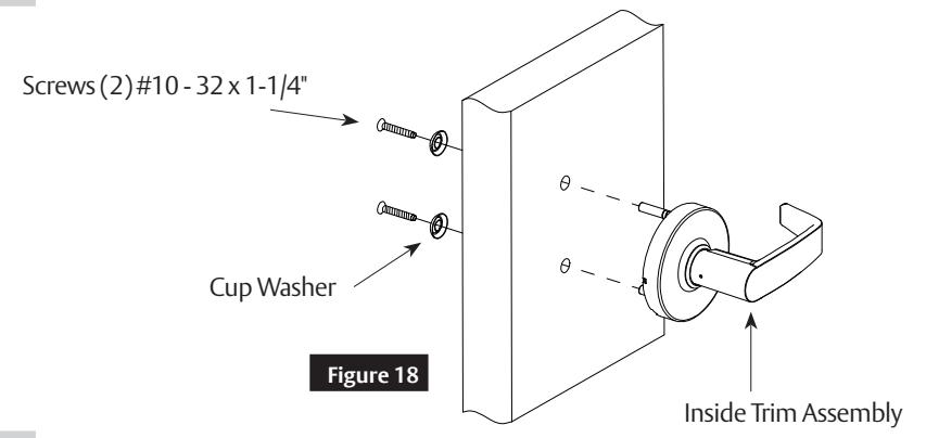
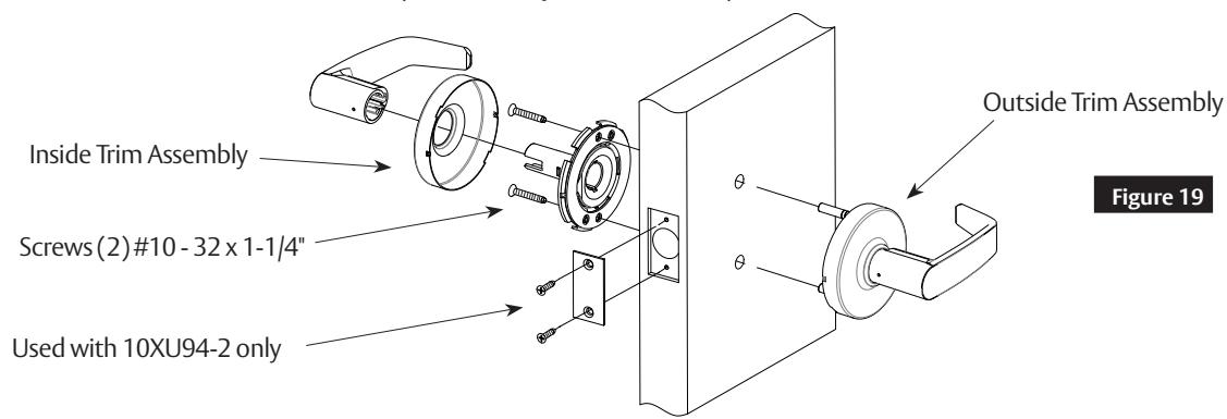
| 5 | Screws - through-bolt (2) #10-32 x 1-1/4" |
| 6 | Lockbody assembly with mounting plate |
| 7 | Outside spring housing assembly |
| 8 | Cylinder spacer |
| 9 | Cylinder |
| 10 | Outside lever handle |
| 11 | Key |
| 12 | Push pin |
| 13 | Latch |
| 14 | Screws - strike (2) #12-24 x 3/4" |
| 15 | Strike |
| 16 | Strike box (Optional) |
3 Door Preparation
- 1. Use template A8290 to mark the door (See Figure 1).
- 2. Drill the door according to the template.
- 3. Verify the dimensions (See Figure 2).
- 4. Install the strike (See Figure 3).
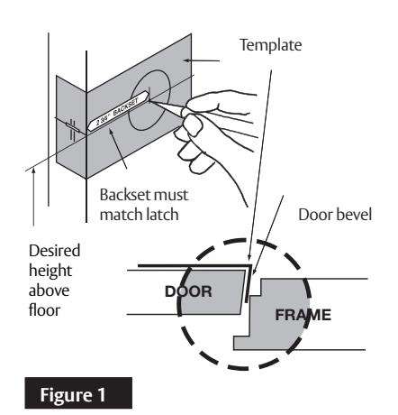
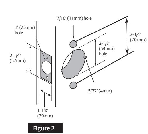
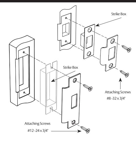
Figure 3
IMPORTANT
- The accuracy of door preparation is critical for proper functioning and security of this lever handle lock. Misalignment can cause premature wear and a lessening of security.
- Be sure to verify backset before marking and drilling door.
Cylindrical Lockset
Installation Instructions
4 Latch Installation
Insert latch in door. (Be sure bevel edge of bolt faces strike plate.) Attach with (2) #8-32 x 3/4" screws supplied.
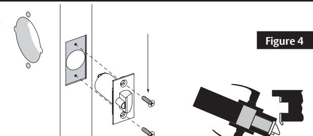
IMPORTANT: Deadlocking latch must stop on strike when door is closed.
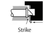
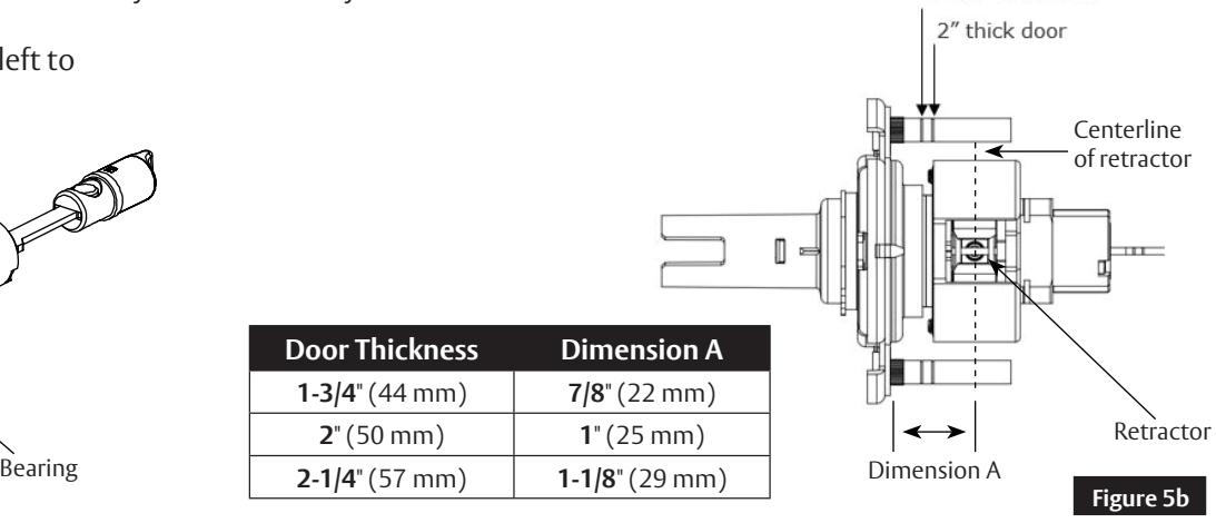
5 Adjust Lock for Door Thickness (if necessary)
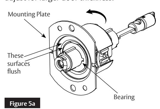
Lock is factory preset for 1-3/4" (44mm) doors unless specified. To adjust lock to door thickness if other than 1-3/4" (44mm):
- 1. Remove trim assembly from the lockbody (See Figure 5).
- 2. Rotate mounting plate to adjust for proper door thickness.
- For 2" thick door the inside face of the mounting plate should be flush with the face of the bearing (See 5a).
- Verify correct position from the markings on the through-bolt stud, or by measuring from inside surface of the mounting plate to the centerline of the retractor (See 5b).
- 3. Reassemble the outside trim assembly to the lockbody.
Spin the mounting plate to the left to adjust for larger door thickness.
6 Install Outside Assembly
To adjust lock to door thickness if other than 1-3/4" (44mm) refer to Section 5.
Insert lockbody into door from outside making sure that lockbody hooks latch case and retractor engages bolt tail(s) (See Figure 6).
DO NOT FORCE. (If lockbody does not engage latch easily, check door preparation for errors.)
Latch bolt tail should be centered in depth of retractor. If it is not, refer to Section 5 to properly adjust the lock for door thickness.
Figure 6
Cylindrical Lockset
Installation Instructions
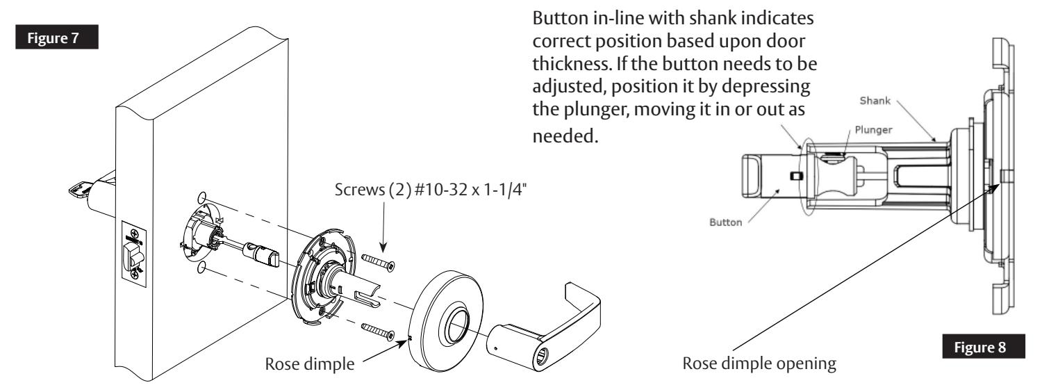
7 Install Inside Components
- 1. Remove rose from inside spring housing assembly.
- 2. Align and insert inside spring housing onto the installed lockbody.
- 3. Install screws to tighten the lock to the door.
- 4. Orient dimples on the side of the rose horizontally at 3 and 9 o'clock position in line with the openings on the spring housing assembly (See Figure 7).
- 5. Install rose onto the inside spring housing assembly.
- 6. In the unlocked position, verify the button is adjusted properly. See Figure 8 for proper alignment. Adjust if necessary.
- 7. Install inside lever.
Note: Test for proper operation before closing door.
8 Cylinder Installation
a Standard Cylinder (Figure 9)
Note:
- For 10XG13 See Section 11 on page 5.
- For 10XG08, 10XG26, 10XG30, 10XG37, 10XG38, 10XG53, & 10XG54 - See Section 10 on page 5.
IMPORTANT
Before installing cylinders:
• Use a flat blade screwdriver to rotate cam until the driver points are in a 6 and 12 o'clock position (See Figure 15 on page 5).
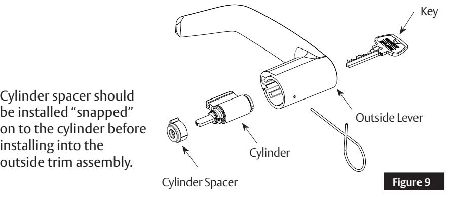
installing into the outside trim assembly.
Cylindrical Lockset
Installation Instructions

8 Cylinder Installation, continued
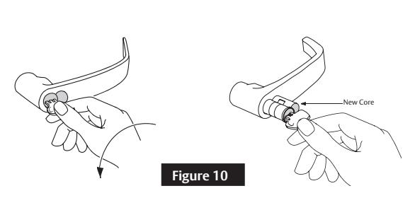
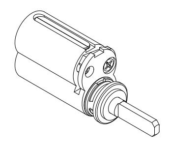
b Interchangeable or Removable Core (Figure 10)
- Remove temporary construction core or plastic core. If keyed, use Control Key (stamped "C") rotate 15° and pull.
- Insert permanent core into lever with control key. Rotate 15° and remove key.
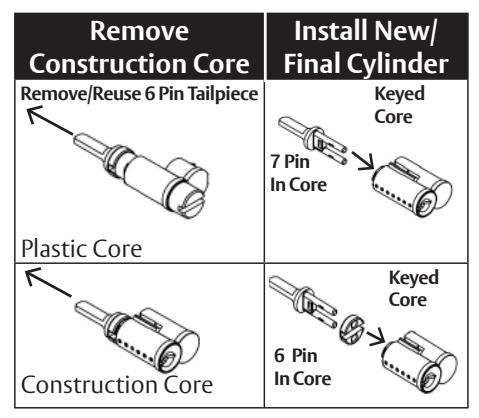
SFIC
IMPORTANT
- Remove tailpiece from construction core and insert into new core. If using 7 pin cores, insert the 7 pin tail piece that's supplied with the lock, before installing the core into the lock.
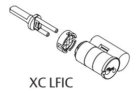
- For XC LFIC cores, snap-on retainer must be installed onto tailpiece. Tail and retainer assembly will press fit onto back of core.
9 Lever Removal & Installation
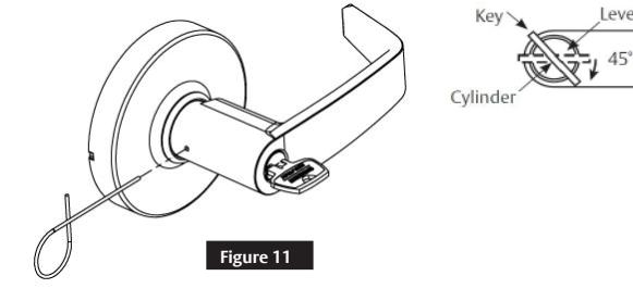
a Standard Cylinder (Figure 11)
To Remove:
Rotate key 45° and hold. Depress lever catch with pin tool.
To Install:
With driver points at 6 and 12 (See Figure 15), rotate key 45° in either direction, and then slide the lever on over the lever catch. Confirm the lever will not pull off.
b Interchangable or Removable Core (Figure 12)
To Remove:
Remove core and tailpiece, using control key (stamped "C").
Insert slotted screwdriver or lever release tool into the cylinder opening and make contact with the lever catch.
Pull lever catch horizontally towards the opposite side of the cylinder opening and remove lever. *Note
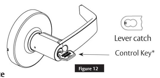
For 1-Bitted cylinders, utilize a control key cut 113511.
To Install:
Without the core installed, slide the lever over the lever catch. Confirm the lever will not pull off. Install core and tailpiece, using control key (Stamped "C").
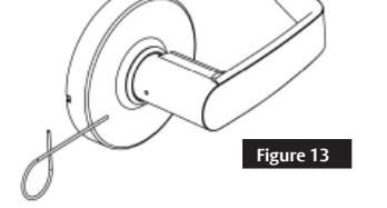
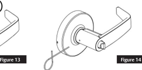
c Plain Lever (Figure 13) & Push/Turn Button (Figure 14)
To Remove:
Depress lever catch with pin tool, remove lever.
To Install:
Slide lever on over the lever catch. Confirm the lever will not pull off.
1-800-727-5477 • www.sargentlock.com
4 Copyright © 2021-2023 SARGENT Manufacturing Company. All rights reserved. Reproduction in whole or in part without the express written permission of SARGENT Manufacturing Company is prohibited.
Cylindrical Lockset
Installation Instructions

10 Lock Timing
Timing is required if cylinders were not provided factory installed. To verify and adjust timing:
a Functions 10XG08, 10XG26, 10XG30, 10XG37, 10XG38, 10XG54
- 1. Remove cylinder lever(s) to view internal cam (See Figure 15).
- 2. Adjust internal cam on each side that has a cylinder. To adjust:
- a. Use a slotted screwdriver to rotate cam fully counterclockwise.
- b. Confirm that the cam is now at the 6 and 12 o'clock position.
- 3. Re-install levers with cylinders (See Section 9a).
- 4. Test cylinder(s) with key before closing door.
- 5. Confirm outside key rotates 360° in both directions from the shed position.
- 6. If outside key does not rotates 360°, repeat steps 1-5.
b Function 10XG53 Internal Cam
- 1. Remove cylinder lever to view internal cam (See Figure 15).
- 2. Adjust internal cam using a slotted screwdriver rotating fully clockwise.
- 3. Confirm that cam drive points are at the 6 and 12 o'clock positions.
- 4. Re-install lever (See Section 9a).
- 5. Test cylinder with key before closing door.
- 6. Key should rotate approximately 225° counterclockwise from shed position to lock and less than 90° from shed position to unlock.
- 7. Repeat steps 1-6 if necessary to correct timing.
11 Other Instructions
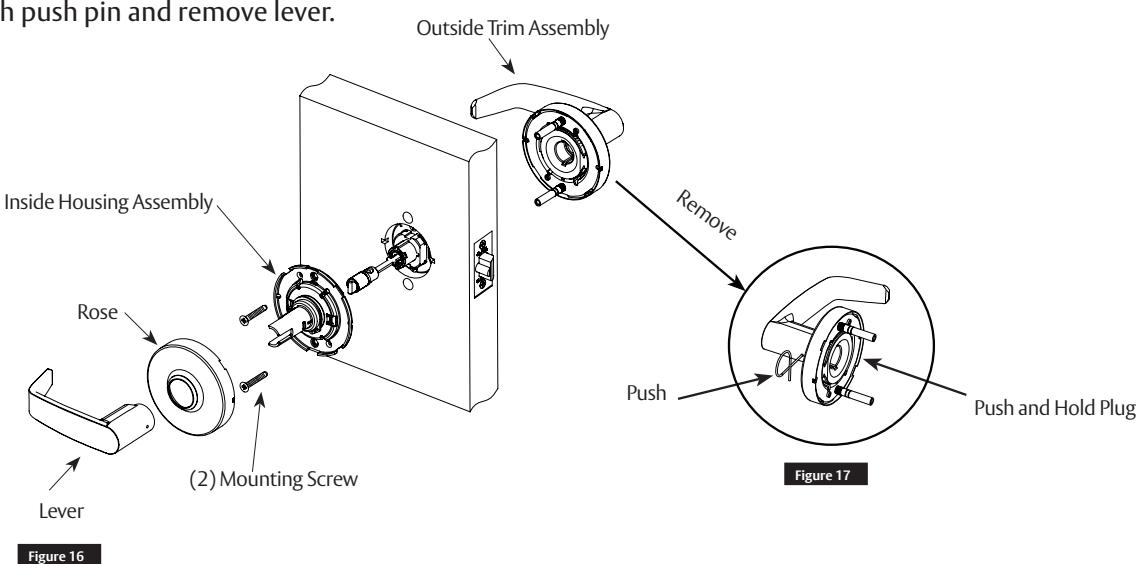
a Remove Outside Lever for Exit Latch 10XG13
- 1. Remove inside lever (See Section 9).
- 2. Remove rose.
- 3. Remove (2) mounting screws and inside housing assembly (See Figure 16).
- 4. Remove outside trim assembly.
- 5. Push and hold plug back (located inside of outside trim assembly). See Figure 17.
- 6. Push lever catch with push pin and remove lever.
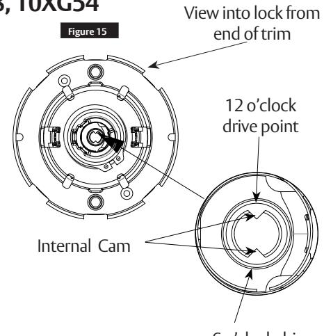
6 o'clock drive point
Cylindrical Lockset
Installation Instructions
11 Other Function Instructions, continued
b Install Single Lever Pull 10XU93
c Install Double Lever Pull (10XU94/ 10XU94-2)
12 Miscellaneous Options
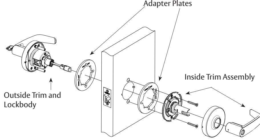
a 1-3/8" Doors (1- Option)
Install (1) adapter plate between the door and rose assemblies (both sides).
- Inside trim to be aligned with holes marked screw slot.
- Outside trim through-bolts to be aligned with through-bolt holes marked on adapter plate.
Cylindrical Lockset
Installation Instructions
12 Miscellaneous Options
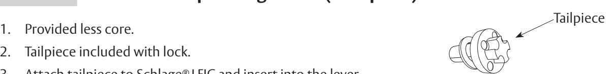
b Lever to Accept Schlage® LFIC (SF- Option)
- 2. Tailpiece included with lock.
- 3. Attach tailpiece to Schlage® LFIC and insert into the lever.
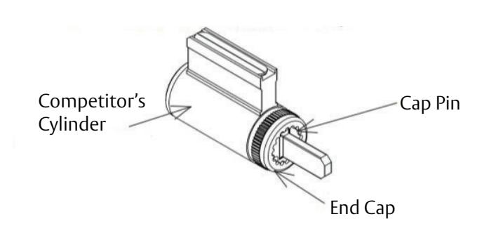
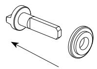
c Lever to Accept Schlage® or Yale® Fixed Core Cylinder (30- or YC- Option)
- 1. Provided less core.
- 2. Depress cap pin and unscrew end cap to remove tailpiece from competitor cylinder.
- 3. Insert new tailpiece, in orientation shown.
- 4. Re-assemble end cap over new tailpiece.
d Lever to Accept Yale® LFIC (YRC- Option)
- 1. Provided less core.
- 2. Slide provided spacer over tailpiece
3. Insert driver assembly into back of core.
Cylindrical Lockset
Installation Instructions

12
Miscellaneous Options
e
10XG50 Hotel Function Timing Adjustment
Timing of the hotel cylinder is set at the factory for the standard door thickness. If the change key or emergency key does not operate properly, follow the steps below:
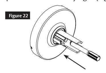
- 1. Set the lock to the unlocked position, remove lever and cylinder from the outside trim. See lever removal instruction on page 4).
- 2. Insert adjustment tool (provided with lock) into interior cap located within the shank (Figures 22 & 23).
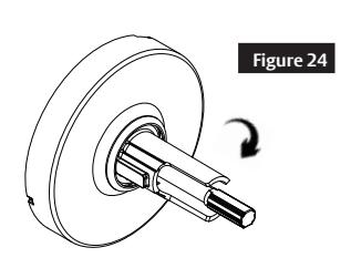
- 3. Rotate cap clockwise until fully tight (Figure 24).
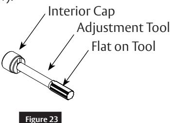
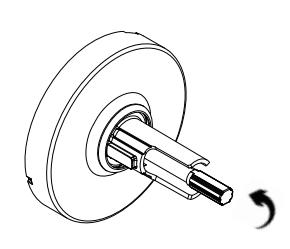
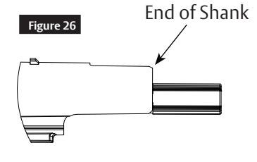
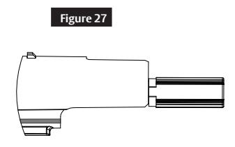
4. Rotate cap back counter-clockwise (Figure 25) until tool handle is approximately in line with the end of the shank as shown in Figure 26 for Fixed Core cylinder (FC) or in Figure 27 for Interchangeable Cylinder (LFIC). The flat on the tool should be at the 12 o'clock position.

- 5. Install cylinder in the lever (see cylinder installation instruction on page 3).
- 6. Turn key 90 degrees counter-clockwise and install lever (with cylinder) onto shank.
-
7. Test to confirm that both the operating and the emergency keys work properly in both the unlocked and locked (pushed/pushed and turn) positions.
- If the operating key is still working in the locked position, the interior cap needs to be turned out (CCW) 1/2 turn.
- If the emergency key is not working in the locked position, the interior cap needs to be turned in (CW) 1/2 turn.
Troubleshooting:
- If having issue fine tuning the adjustment, re-start from #3.
- If cylinder will not install, re-start from #3.

A8286-FN-4 5/23